Your reliable photonics partner ! 


        Optical Coating

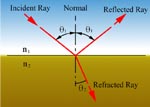
Whenever light passes from one medium into another medium with different optical properties, most notably refractive index, part of the light is reflected and part of the light is transmitted. The intensity ratio of the reflected and refracted components is a function mainly of the difference in refractive index among the materials, the polarization of the incident light and the angle incidence.
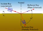
        According to Fresnel's
law, it is convenient to think of incident radiation as the superposition of two plane-polarized beams, p-polarized which electric field paralled to plane of incidence and s-polarized which electric field perpendicular to the plane of incidence. Frenel laws can be summarized the following two equation:

        When reflected and refracted rays are perpendicular to each othere(q1+q2= 90), the reflected light is completely s-polarized. This angle is called Brewster angle.
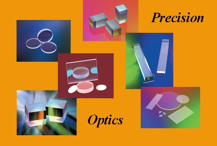
        Optical coatings are used to alter the reflectance, transmittance, absorbance, or polarizer properties of optical components. The optics being coated is usually called the substrate. 
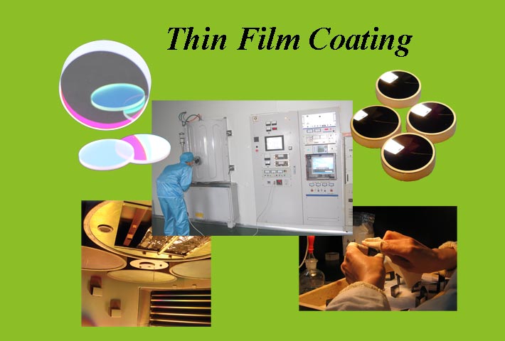
The coating is deposited in high vacuum using the process of evaporation by either e-beam, resistive heat or IAD(Ion Assisted Deposition) in conjunction with an e-beam source. We can also offer coating done with an APS( Advanced Plasma Source) by Leybold. This technique combines the advantages of IAD coatings and ion plating without some of the drawbacks associated with ion plating. We can offer state-of-the-art equipment, advanced design software and highly experienced engineers to provide you with absolutely the highest level of support. Coating material include metal (Au, Al, Ag, Ni-Cr, Cr and so on), dieletrics(Oxides, Fluorides and Sulfides) and semiconductors(Si, Ge).

        Optical interference coatings respond differently to s and p polarized light. For this reason, it is essential to specify s, p, or random (the average of the s and p performance) polarization when the angle of incidence exceeds 20 degrees.


Definitions:
R0: Reflectance at central wavelength   Tp: Transmittance for p-plane polarization
Rs: Reflectance for s-plane polarization    R: Reflectance for random polarization
Rp: Reflectance for p-plane polarization             R = (Rs + Rp) / 2
Ts: Transmittance for s-plane polarization T: Transmittance for random polarization
                                                                          T = (Ts + Tp) / 2

Coating methods:

To make an coating there are many different techniques that may be used. In this section we will briefly review the techniques that we use in Simphoton. We two main techniques, resistive heating (thermal evaporation) and e-beam evaporation. We can augment the e-beam technique with ion assisted deposition (IAD) and a technique provided by Leybold called advanced plasma source (APS).

Resistive heating:
In this technique the coating material is placed in a "boat" enerally made of molybdenum, platinum or tungsten. This boat is heated by running a low voltage current through it, which causes the coating material to evaporate into the chamber. While this techniques works well for some materials it does not produce the best coatings for some applications. Furthermore, some materials cannot be vaporized in this manner since the vaporization temperature may be too high.

E-beam coatings:
In e-beam coatings the coating material is placed in a small, water cooled crucible. A electron beam (5-15 kV) is focussed into the crucible in a very small spot. This spot is then "swept" round the crucible heating the material. The small spot size of the beam means that the temperature can be very high, high enough to evaporate refractory materials.


Enhancements to e-beam coatings:
An e-beam coating can be further enhanced by the use of an ion beam. Ion assisted deposition (IAD) is used to improve the films’ composition. This is particularly true for oxides, nitrides and carbides where the stoichiometry of the film can be controlled. IAD can also assist in reducing the films' stress and in film densification. Another recent development, is the Advanced Plasma Source (APS) offered on the Leybold coaters. This technique provides for additional densification of the film and stoichiometric control of the film like that in IAD. It also provides a very adherent, smooth film like that provided in ion plating. However, it can also be used on organic substrates (unlike ion plating).

Quality
We can provide spectral curves from out Perkin-Elmer 900 (UV/VIS/NIR) spectrophotometer on all of our coatings.

Our coatings meet the Standard Mil Spec tests shown below:
1. Abrasion, Mil-C-675A
2. Adhesion, Mil-M-13508C
3. Hardness, MIL-M-13508C


Materials for coatings and properties

Materials Evaporation Technique Refractive Index Region of Transparence Remarks
Al2O3 Electron bombardment 1.62at0.6mm(Ts=300o)
1.59at1.6mm(Ts=300o)
1.59at0.6mm(Ts=40o)
1.56at1.6mm(Ts=40o)
  Can also be produced by anodic oxidation of Al in ammonium tartate solution
HfO2 Electron beam 2.088 at 350nm
2.00 at 500nm
220nm-5mm  
LaF3 Tungsten boat 1.59 at 550nm
1.57 at 2mm
220nm-12mm Slightly inhomogeneous substrate heated
LaF3 Tungsten boat 1.59 at 550nm
1.57 at 2mm
220nm-12mm Slightly inhomogeneous substrate heated
MgF2 Tantalum boat 1.38 at 550nm
1.35 at 2 mm
210nm -10mm Films on heated substrates much more rugged. High tensile stress
SiO2 Mixture in tungsten boat. Electron beam 1.46 at 500nm
1.445 at 1.6mm
<200nm-8mm(in thin films)  
Ta2O5 Electron beam 2.16 at 550nm 300nm-10mm  
TiO2 Reactive evaporation of TiO or Ti2O3 in O2 Electron beam reactive evaporation 2.2-2.7 at 550nm depending on structure 350nm-12mm Can also be produced by subsequent oxidation of Ti film
Y2O3 Electron beam 1.82 at 550nm 250nm-2mm  
ZnS Tantalum boat or howitzer 2.35 at 550nm
2.2 at 2.0mm
380nm-~25mm  
Copyright Simphoton Optronics Co., Ltd. All rights reserved.